
A replaceable cable-entry plate lets an OEM support several connector or gland layouts without changing the main enclosure. The idea is simple: keep one chassis opening and exchange a smaller plate. The challenge is maintaining the mechanical interface when the cutouts, hardware and cable loads change.
The plate should be treated as a controlled subassembly, not as spare flat stock drilled near the end of production. For an industrial computer enclosure, the entry interface can affect assembly time, service access, environmental protection and the ability to supply consistent variants.
Freeze the common envelope first
Define the main opening, mounting-hole pattern, seating surface and plate outside profile independently of the variant cutouts. Identify the datum scheme used for both the enclosure and the plate. Where the plate is asymmetric, include an orientation feature that prevents incorrect installation.
Then define the interchangeable variants within that boundary. A buyer can approve a new gland pattern without reopening the chassis interface if the change remains inside the controlled envelope. Revision control should still connect the variant drawing to the correct assembly bill of material.
| Keep common | Allow by variant | Recheck when changed |
|---|---|---|
| Mounting pattern and outer envelope | Released gland or connector cutouts | Tool access and local stiffness |
| Seating land and fastener arrangement | Approved cable hardware | Gasket contact and installed height |
| Orientation and drawing references | Variant identification | Assembly and service instructions |

Specify the gasket contact as an interface
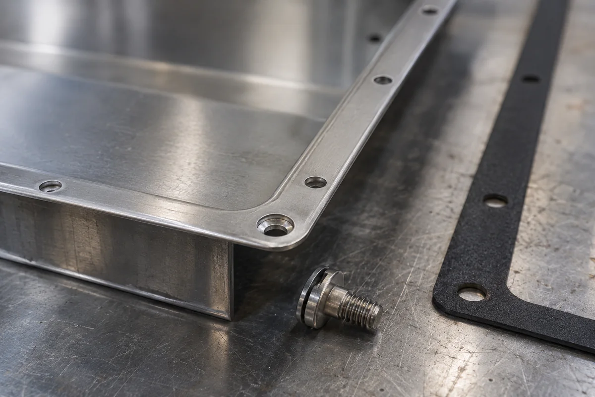
If a gasket is used, identify its part number or released specification, seating land and compression arrangement. Cutouts or fasteners too close to the contact path can change the seal geometry. Surface finish and coating buildup may also affect the assembled joint.
A gasket fitted to a plate does not establish an enclosure ingress rating by itself. The complete construction, including glands, fasteners and installation, must meet the project’s validation requirements. Avoid printing an IP value on a fabrication drawing as though it were proven by the plate outline alone.
Show whether the gasket stays with the enclosure or the removable plate. That choice affects replacement parts, service handling and the risk of damaging the sealing surface during maintenance.
Check hardware and tool space on both sides
A gland requires more space than its panel hole. Include the outside body, internal locknut, wrench access and any adjacent cable-support hardware. Closely spaced cutouts may look acceptable in a flat pattern but leave no practical way to tighten the installed hardware.
Define the selected gland’s permitted mounting thickness and opening details from its own documentation. If the plate needs local reinforcement, confirm that the added thickness remains compatible. Do not assume one hole diameter or thickness works for every nominal cable size.
Support cables without making the plate a handle
Cable routing can apply loads during assembly, maintenance and transport. Identify where those loads are restrained. A thin removable plate should not be assumed to carry the weight or handling force of an unsupported bundle.
Provide strain-relief and support features appropriate to the selected harness arrangement. Preserve bend radius and space to disconnect the cable when the plate or neighboring cover is removed. Where service access requires releasing a support, document that sequence.
The environment also matters. Rittal’s discussion of enclosure moisture explains why condensation must be considered separately from visible water entry. A tightly closed entry plate does not solve every moisture mechanism.

Purchase variants with an interface checklist
For equipment with a defined shielding boundary, review the removable cable bulkhead guide as well. It adds connector-to-plate contact surfaces, perimeter continuity and configuration-specific electrical verification to the variant checklist.
Supply a common interface drawing, the variant matrix, selected hardware data and finish requirements. Define whether the quotation includes the bare plate, fitted gasket, installed glands or cable assembly. Keep environmental validation as an explicit line item with its own conditions.
For repeat orders, check the mounting pattern and seating features against the released revision, then inspect variant-specific cutouts. This creates an interchangeable product family without treating every cable arrangement as a new enclosure design.
Where the same equipment includes a removable sheet-metal fan tray, coordinate cable supports and disconnection access with the tray’s extraction path. Replacing one plate variant should not trap another serviceable module.
Need a Custom Sheet Metal Quote?
Send us your CAD drawings — DRAmetal's initial response target is within 24 working hours. Quotation, DFM and lead-time timing depend on file completeness and engineering scope.
GET A FREE QUOTE →

