Sheet metal embossing can increase panel stiffness without changing the starting sheet gauge. It moves part of the sheet out of plane, but it does not guarantee a fixed stiffness gain or a lower total cost than increasing thickness. The result depends on rib geometry, material and temper, load direction, panel supports, forming limits, tooling and production volume.
This guide covers how embossing actually adds stiffness, the design patterns that work, depth and spacing rules, and when embossing is the right answer versus other stiffening approaches.
Quick summary — Embossing can increase bending resistance without adding sheet stock by creating an out-of-plane section. There is no universal rib-depth ratio or stiffness multiplier: material, thickness, feature radii, panel size, load path and boundary conditions all influence the result. Use a section-property calculation for screening, then verify the selected geometry with FEA and, where performance matters, a formed sample or prototype test.
Why Embossing Works (The Physics)
Bending stiffness of a sheet is proportional to section moment of inertia, which depends heavily on out-of-plane distance from the neutral axis — specifically, distance cubed.
For a flat sheet:
I_flat = b × t³ / 12For an embossed sheet with a rib of depth h:
I_embossed ≈ I_flat + A_rib × d²Where d is the distance from the rib area to the section’s neutral axis. Moving material away from that axis can increase section moment of inertia, but the simplified expression does not capture local thinning, corner radii, residual stress, panel supports or load direction. Those factors must be included in the engineering validation.
Why a fixed stiffness multiplier is misleading
A useful comparison keeps the material, panel envelope, load case and support conditions constant, then evaluates:
- the flat-panel baseline;
- one or more candidate rib profiles and orientations;
- predicted deflection, stress and local buckling under the actual load case;
- forming strain, thinning and springback; and
- prototype measurements against the drawing’s acceptance criteria.
A hand calculation can rank concepts, but it should not be presented as the expected production stiffness. Use FEA with realistic boundary conditions and validate the final design on a formed sample when stiffness is a critical-to-quality characteristic.
Why this matters
Cantilevered panels, covers, electronics housings and large flat sheets may be governed by deflection or vibration rather than material strength. Embossing, a gauge change, formed flanges and added supports should therefore be compared as complete manufacturing options. Tooling, cycle time, scrap risk, inspection and production volume can outweigh material savings, so cost and stiffness must be evaluated for the actual part rather than inferred from a generic multiplier.
Embossing Patterns
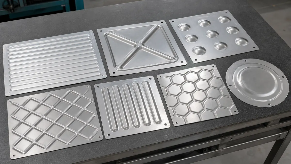
Linear ribs
Single or parallel raised lines running along the sheet. Most common pattern.
| Geometry | Use |
|---|---|
| Round-bottom rib | Standard stiffening, general use |
| Trapezoidal rib | Can increase stiffness with more formed surface area; result depends on geometry |
| V-section rib | Can provide strong directional stiffening but may be harder to form |
Best for: stiffness along one axis (the rib axis stays stiff; perpendicular axis still flexes)
Cross-pattern ribs
Two sets of ribs crossing perpendicular. Higher 2D stiffness but more complex to form.
Best for: panels needing biaxial stiffness, electrical chassis covers, large flat shrouds
Dimples (round embossings)
Circular raised features distributed across the surface. Each dimple is a localized stiffener.
| Pattern | Use |
|---|---|
| Grid pattern | Uniform biaxial stiffening |
| Diamond pattern | Geometry-dependent biaxial stiffening with a distinct visual pattern |
| Concentric ring | Center-of-panel reinforcement |
Best for: cosmetic surfaces where linear ribs would look industrial, lightweight stiffening
Honeycomb / hex embossing
Hexagonal raised cells that can improve stiffness-to-weight performance when the geometry, material and boundary conditions are validated.
Best for: aerospace panels, racing chassis, lightweight applications where appearance is acceptable
Beads (long thin raised lines)
Narrower than ribs, often along edges. Used for both stiffening and edge protection.
Best for: panel edges, longitudinal stiffening on long thin parts
Design Rules
Depth-to-thickness ratio
Depth is a design variable, not a universal multiple of sheet thickness. A deeper feature may raise section height, but it also increases forming strain, thinning and springback. The feasible depth must be established for the exact material specification and tool geometry.
| Design input | Why it matters | How to verify |
|---|---|---|
| Material, temper and thickness | Controls ductility, thinning and springback | Material certificate plus forming review |
| Rib width, flank angle and radii | Controls material flow and local strain | Tooling review and forming simulation or trial |
| Panel size and supports | Changes the dominant deflection mode | FEA using the real boundary conditions |
| Load direction and attachment points | Determines whether the rib intersects the load path | Load-case review and prototype measurement |
| Coating and cosmetic requirement | May limit allowable stretch and surface marking | Sample approval against the finish specification |
For a 2 mm sheet—or any other gauge—do not scale a generic depth range directly into the drawing. Start with a manufacturable concept, review it with the fabricator, and release the depth and profile as drawing-controlled dimensions only after analysis or sample validation.
Spacing
Embossings placed too close together can create overlapping strain zones and difficult material flow; features placed too far apart may leave an unsupported panel region. Set spacing from the proposed feature width, tool access, material behavior and the deflection shape predicted for the actual load case. Confirm the layout during DFM review and, for stiffness-critical panels, correlate the FEA model with a formed sample.
Edge distance
Embossings too close to a sheet edge or bend cause:
- Edge deformation
- Cracking at the emboss flank
- Bend interference (if near a bend line)
| Location | Review requirement |
|---|---|
| From sheet edge | Leave enough material for forming flow without edge pull-in or tearing |
| From bend line | Separate the strain zones and confirm the forming sequence |
| From holes and cutouts | Check distortion, ligament strength and inspection access |
| From another emboss | Avoid overlapping forming zones unless the tool is designed for the combined pattern |
Edge and bend clearances should be agreed during DFM review and recorded on the released drawing; they should not be inferred from a universal multiplier.
Corner radii
Sharp internal transitions can concentrate strain and promote cracking. Use smooth internal and external transitions, then select the radii from the material’s formability, feature depth, tool construction and surface requirement. Put the approved radii on the drawing and validate the most highly strained locations during first-article inspection.
Material Considerations
| Material | Embossing Performance |
|---|---|
| Mild steel (CRS) | ✅ Excellent — most forgiving |
| Stainless 304 / 316 | ✅ Good — work-hardens but forms well |
| Aluminum 5052 | ✅ Good — typical sheet metal alloy |
| Aluminum 6061-T6 | ⚠️ Limited — already heat treated, less ductile |
| Galvanized steel | ✅ Good — coating accepts stretch |
| Pre-painted steel | ⚠️ Limited — paint may crack at deep embosses |
| Hardened materials | ❌ Not embossable in hard condition |
For grain direction sensitivity, see our press brake bending defects guide.
Embossing vs Alternative Stiffening Methods
| Method | Expected structural effect | Commercial / manufacturing consideration | Best for |
|---|---|---|---|
| Increase thickness (flat) | Raises plate bending rigidity in both axes | More material mass; may avoid feature tooling | When a gauge change meets all interfaces and weight limits |
| Embossed rib (single) | Directional improvement governed by rib and load orientation | Requires forming review and may require dedicated tooling | Panels with a defined weak axis |
| Cross-ribbed pattern | Can address biaxial panel deflection | More complex material flow and tooling | Biaxial stiffness requirements |
| Welded gusset | Adds stiffness near a load or attachment point | Adds components, weld distortion and inspection | Concentrated load paths |
| Bend-formed flange | Increases edge-section depth | May change the usable envelope | Sheet-metal edge stiffening |
| Hemmed edge | Stiffens and finishes an edge | Adds forming operations | Cosmetic or handled edges |
| Composite sandwich | Can provide high panel rigidity at low mass | Different supply chain, joining and inspection needs | Weight-critical specialty structures |
The table is directional only. Compare candidate concepts under the same loads and boundary conditions; do not use it as a stiffness or cost quotation.
For comparison with other DFM features, see our hem & seam design patterns.
Tooling and Manufacturing
Production methods
Hard tooling (high volume):
- Stamping press with dedicated emboss die
- Can provide repeatable feature geometry after tool prove-out
- Commercial fit depends on annual quantity, tool life, press selection and amortization
Soft tooling (low volume):
- Press brake with custom embossing dies
- May suit prototypes or lower-volume validation
- Feasibility depends on feature length, access, repeatability and the available machine
Hydroforming:
- Specialized process for complex 3D embossing
- May suit complex shapes when conventional die access or material flow is limiting
- Requires a process-specific supplier and quotation
For tooling cost analysis, see our tooling cost guide.
Springback
After embossing, elastic recovery can reduce the final feature depth. The compensation is material-, geometry-, grain- and process-dependent; it should be established through forming simulation, tool tryout or measured sample data rather than a universal over-form percentage. Production acceptance should use the drawing’s defined datums, profile or depth tolerances.

Common Applications
| Application | Pattern Used |
|---|---|
| Electrical chassis covers | Linear cross-pattern ribs |
| Computer cases / server panels | Honeycomb pattern |
| Appliance side panels | Concentric or diamond pattern |
| HVAC duct stiffening | Longitudinal beads |
| Industrial machine guards | Linear ribs + perimeter beads |
| Aerospace interior panels | Hex / honeycomb |
| Automotive structural panels | Specific stamping patterns |
| Battery enclosure floors | Cross-pattern with thermal management |
Related customer project: EV Battery Tray: Sealed Lightweight Construction. Related resources: EV battery tray and pack enclosure manufacturing page.
An embossed panel should also be evaluated in its installed state. Rails, gaskets, hinges, fastener preload and adjoining panels can change the boundary conditions that governed the original stiffness decision. If acceptance depends on those assembled interfaces, include the feature and mating-component controls in the sheet metal assembly service review rather than approving the loose panel alone.
Common Mistakes
| Mistake | Consequence |
|---|---|
| Emboss depth too low | No real stiffness improvement |
| Emboss depth too high | Cracking, material thinning, failure |
| Sharp internal corners | Stress concentration, fatigue cracks |
| Embossing too close to bends | Bend distortion, cracked emboss flank |
| Embossing too close to edges | Edge deformation, material tear |
| Same depth for different sheet thicknesses | Inconsistent stiffness across panel |
| Cross-pattern in cosmetic surfaces | ”Industrial” appearance |
| Embossing on heat-treated material | Won’t form, or cracks |
When NOT to Use Embossing
| Situation | Better Alternative |
|---|---|
| Cosmetic class-A surfaces | Use back-side ribbing, then cover |
| Liquid-tight surfaces | Embossing creates stress paths — flat is better |
| EMI shielded enclosures | Embossing creates surface variation that hurts shielding |
| Already-thick plate | Stiffness is sufficient without embossing |
| Aerospace fatigue-critical | Specific embossing designs only, with stress analysis |
How DRAmetal Handles Embossing
Our embossing capabilities:
- Pattern review: linear, cross, dimple, honeycomb or drawing-defined custom geometry
- Tooling review: select a forming route after quantity, material and acceptance criteria are known
- Depth control: quote against the released drawing tolerance after material, geometry, tooling and inspection-method review
- DFM review: assess depth, spacing, radii and edge clearance for manufacturability
- Material review: confirm alloy, temper, thickness, grain and coating before accepting the feature
For our DFM 17-point checklist and sheet metal punching services, see our pages. To request an embossing review, submit your CAD. The initial response target is within 24 working hours; pattern, depth and stiffness feedback depends on geometry and engineering review.
Bottom Line
Embossing can be an efficient way to redistribute the existing sheet section, but it is not a guaranteed stiffness multiplier or a zero-cost change. The benefit and manufacturing cost depend on geometry, material, boundary conditions, tooling and volume. A poorly matched feature can crack during forming or fail to reduce deflection where the load path requires it.
Treat depth, radii, spacing and edge clearance as linked design variables rather than universal ratios. Screen concepts with section calculations, model the real supports and loads in FEA, review formability with the manufacturer, and verify critical performance on a formed sample. Record the accepted geometry and inspection method on the released drawing.
Embossing is not a workaround for incorrect material selection or panel sizing. It is one structural option to compare with gauge changes, flanges, gussets and supports. The production choice should follow validated stiffness, formability, tolerance, quality and cost requirements for the actual part.
Need a Custom Sheet Metal Quote?
Send us your CAD drawings — DRAmetal's initial response target is within 24 working hours. Quotation, DFM and lead-time timing depend on file completeness and engineering scope.
GET A FREE QUOTE →

